This is the second part of several posts. I will be explaining about what I did to prepare the rover for the arduino and breadboard.
Links:
Part 1: Initial Plan and Reverse-Engineering
Part 2: Preparing the Rover Chassis
Part 3: Motor control
Part 4: Bluetooth
Part 5: Mounting
Part 6: Batteries
Part 7: The Test
Naturally, the first thing to do was to disconnect the two halves. The wires from the motors are soldered to different wires coming out of the brain box, so I cut them about halfway to the brainbox from the solder:
Motor----------=====----- -----Box
The tubing over the joint slid off, and the insulation on the box-side of the wire followed. Unfortunately, the wires were all threaded, making any connections to a breadboard tedious to say the least. To fix this, I found some wire of the proper diameter (about 22 American Wire Gauge), and soldered it to the motor wire. This gave me more length (and thus more design flexibility), and allowed me to directly connect them to a breadboard.

I am by no means the best at soldering, but it works. I tested each joint to make sure it was strong enough to withstand much more tension than it would ever practically have to take. I also probably should have used color coding for the wires, but... I didn't want to make a bigger mess by opening the black spool. Silly me wound up opening it anyway about 15 minutes later.
Next, I had to replace the wires originally on the battery case with proper 22 AWG wire. All of the connections on the battery case were covered in glue, so I had to pry that off with my nails before using the soldering iron. The wires came off pretty easily, and I was able to reuse some of the solder that was still clumped on the metal case lead for my own wires. This time, I used the black wire for the negative side. While doing this, I noticed that my soldering iron could melt through the plastic. I also found that the heat could make the cheap plastic insulation on the original wires disappear.
That left the headlight as the only thing keeping the guts connected to the chassis. Removing it required unsoldering it from the rest of the guts. In the process, I liberated a devil-resistor (666 ohms according to my multimeter when I first measured it. D: ) from the wire leading to the broken headlight.
After that, none of the original guts remained inside the rover except for the gearbox and some foam that I meant to leave in.

If anyone's interested in my soldering tools, here's a picture:
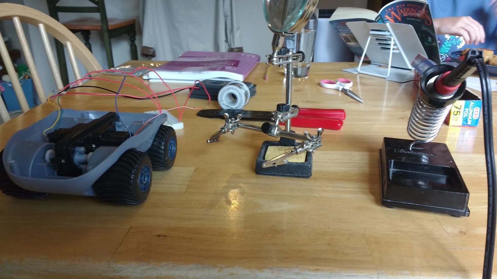
Here's a list of my equipment:
One 20 watt soldering iron from Radio Shack
One spool of solder, also from Radio Shack
One soldering multi-tool with alligator clippers and magnifying glass... from Radio Shack.
One soldering iron holder... from Radio Shack. Be very careful with the sponge that comes with this. It ate one of my soldering iron tips... You've been warned!
Part 3 will be about my troubleshooting, desperately trying to get the motors to work with Arduino.
As with last time, I have some tips:
1. Plan out what you're going to do beforehand. Don't just shove the soldering iron wherever you see something shiny. ;)
2. Patience is your best friend. Sometimes solder will take a while to absorb enough heat. Give it time. If it heats your fingers holding the solder tube but doesn't melt, maybe you should chop off the tip and keep trying (Works for me.).
3. Be careful to make sure your solder sponge isn't hungry. No idea why, but I've put my hot soldering iron onto the holder's wet sponge... and over time it's eaten away at the iron tip.
4. This might belong in the Part 2, so I'll put it there too: The wires from the motors connect to wires from the brain box via solder. The heat-shrink tubing wasn't connected very well on mine, so I could slide that away from the solder, and after snipping the wires on the brain-box side of the connection, I could just slide the insulation right off.
What should I do with the devil-resistor? Should I...
A: Throw it away
B: Try to get it to explode (Or something exciting) by trying to overload it... I'll include a video.
C: Chop it in half
D: Give the innocent resistor a chance... It's never done anything to me (yet)
Edit: 5/11/16: Updated list of links
Edit: 6/1/16: Updated list of links
Edit: 7/8/16: Updated list of links
Edit: 8/25/16: Updated list of links
Edit: 7/6/17: Updated list of links
No comments:
Post a Comment
I've been forced to enable comment moderation. Your comment will now have to be looked over before it's allowed.
I'd love to hear from you, but unfortunately, jerk spammers have been taking advantage of commenting. They've been using it as advertising for BAD stuff.
Spammers, please don't make me get out the ban-hammer.
This is why we can't have nice things.