Showing posts with label Arduino. Show all posts

Thursday, July 6, 2017

Arduino Part 7: The Test

A few weeks ago, I picked up the Arduino Uno that I've had for a while, and started thinking about what I should build with it. I decided on modifying an old toy rover that I had, and making it wirelessly drivable... but with 2 way audio and a camera feed. single-frame camera-broadcast.


Links:
Part 1: Initial Plan and Reverse-Engineering
Part 2: Preparing the Rover Chassis
Part 3: Motor Control
Part 4: Bluetooth!
Part 5: Mounting
Part 6: Batteries
Part 7: The Test

- Chassis: Check
- Motor Circuitry: Check
- Bluetooth Functionality: Check
- Android App: Check
- Arduino Mount: Check
- Power: Check
- Double Check: Check

Now what happens when I put it together and turn it on?

On May 18th, I put batteries into the compartments. I put the Arduino on the rover. I plugged all of the motors into the breadboard, with their uncomfortably long wires. I plugged in the positive power. I checked the circuitry twice for errors, and tried to think of any solder joints that might need to be changed.

My mom helped me record the first test.
Here are 4,249 pictures of it:


Success

Since then, I've stopped working on it... I still might set up an audio system. In theory, it won't be nearly as complicated as a camera system, requiring less bandwidth to work.

Speaking of cameras and bandwidth, an image-broadcasting system, unfortunately, isn't practical. Even at 480x360p, black and white (One byte per pixel), each image would be 1.4 Mb, or 172.8 kB. The Arduino Uno has only 2kB of SRAM... Way too little to store an image. Plus, even at a baud rate of 115,200, it would take 12 seconds to broadcast. In my calculations in part 4, I mistook 115,200 to be the number of bytes, rather than bits, per second, so I thought it would only take 2.66 seconds per frame (with 78% more pixels).

Here are the project's credits:

Myself:     Designer, builder, programmer
My mom:  Inspired me to do this project, and lets me explain problems to her
My dad:    Sponsor and design help

Thursday, August 25, 2016

Arduino Part 6: Batteries

A few weeks ago, I picked up the Arduino Uno that I've had for a while, and started thinking about what I should build with it. I decided on modifying an old toy rover that I had, and making it wirelessly drivable... but with 2 way audio and a camera feed. single-frame camera-broadcast.


This is the sixth part of several posts. I will be explaining about how I set up the power supply of my rover.

Links:
Part 1: Initial Plan and Reverse-Engineering
Part 2: Preparing the Rover Chassis
Part 3: Motor Control
Part 4: Bluetooth!
Part 5: Mounting
Part 6: Batteries
Part 7: The Test

To start with, here are some facts about the situation:
  The rover is only designed to hold three AA batteries (4.5 volts).
  According to my multimeter when monitoring the long-disconnected-and-very-bored rover brain, the motors are designed to get the full 4.5 volts from the batteries.
  Arduino requires, at the very minimum, a stable supply of more than 5 volts.

This makes it more difficult than I originally thought, which was: "Let's just hook up a 9-volt!" Browsing Google search told me otherwise...

I wasn't about to go looking for how to use a switching regulator, so plan B was to use AAs. Three for the motors and four for Arduino means seven batteries total. That's even more than I remember RC helicopter controllers and the Lego Mindstorms NXT using.

Here's Plan B-and-a-half:

1. Test to see how few batteries can successfully power the motors (Two)
2. Add a single battery to the rover (For a total of four)
3. Have a third wire coming from the middle of the battery chain, thus using all of the batteries to power the board while two of those are also powering the motors when necessary.
4. Do extensive tests with my multimeter to ensure that the voltage never drops below 5 volts. If it does, fiddle with the circuitry until it's stable.

After the test was set up, I found that voltage dropped drastically at the moment I started the motors. Voltage would then very slowly increase as the motors weren't requiring as much power to continue spinning. I added the biggest capacitor I had (1000 μF, also referred to as 1mF). This made good progress, but the capacitor was discharging too quickly. This delayed, but hardly reduced, the voltage drop.

To combat this, I added a 1KΩ resistor between the power / capacitor leads and the Arduino Vin wire. This was a mistake because then, while tests showed satisfactory results, trying to power the Arduino didn't work. The resistor was choking Arduino, and my multimeter couldn't tell because it has a very high internal resistance.

My next attempt was to add the resistor in series with the capacitor, leaving the power wire directly connected to Arduino's Vin pin (Or, at first, the multimeter's lead). This was successful. Charging the capacitor wasn't noticeably affecting results, and voltage would slowly drop, but not to the fatal 5V level, when spinning the motors.

The final test went very well. Arduino turned on. Power was stable. (Manually) activating the motors didn't break anything, and Arduino didn't die when I kept the motors going for several solid seconds. Success!


To get the extra battery into the rover chassis, I had to take a AA holder from another kit, solder it up, and tuck it into the Rover. This would, unfortunately, require me to dismantle the rover in order to change all of the batteries, but it's a personal project. It doesn't need to be super simple, especially since I've already got the Arduino sitting directly on top of the other batteries.

More tips... They just keep coming...

1. Do the math! Connecting random batteries would only have gotten me an overpriced blue paperweight.

2. Know your electrical engineering! The long-standing Kerbal convention of "More Power!" would have lead me to use more batteries rather than a capacitor. This would be less efficient and more likely to overheat the Arduino.

Edit: 7/6/17: Updated list of links

Friday, July 8, 2016

Arduino Part 5: Mounting

A few weeks ago, I picked up the Arduino Uno that I've had for a while, and started thinking about what I should build with it. I decided on modifying an old toy rover that I had, and making it wirelessly drivable... but with 2 way audio and a camera feed. single-frame camera-broadcast.


This is the fifth part of several posts. I will be explaining about how I mounted my Arduino and the breadboard to the rover.

Links:
Part 1: Initial Plan and Reverse-Engineering
Part 2: Preparing the Rover Chassis
Part 3: Motor Control
Part 4: Bluetooth!
Part 5: Mounting
Part 6: Batteries
Part 7: The Test

Almost all of the rover's circuitry and coding were done. I had to start thinking about how I would keep the delicate brains from falling out.

One thing was certain: I wouldn't be able to directly put the Arduino onto the rover: Not enough flat space, and I would be taking a chance of damaging it.

To minimize the damage risk, it would be a good idea to have something to mount the Arduino on, like a cushion in-between the rover pieces and the Arduino.

First, I looked at acrylic mounting boards. These were either expensive, or wouldn't get here very timely. I finally chose the totally-professional-looking recycled-cardboard and string approach.

Steps I took were:
Marked locations for holes with Ultra Fine sharpie through Arduino's.
Punched holes with some sharp screws I had lying around.
Found that the ink was conductive and had to repeat steps 1 and 2 on another piece.
Tied Arduino on with super thin threads.

Just under the top piece of plastic (supposedly designed to give the impression that it was a tinted windshield) was the battery cover. It was long enough that, with some modifications, the Arduino could fit on it sideways. There were two supporting triangles in the way, and I had to find a way to chop off the excess.

Sorry. This image was taken after I chopped it up.

Remember how I said that my soldering iron cut through the plastic way back in Part 2? (In between the first two images) That gave me an idea: I could melt through the plastic and remove just enough. Searching on the internet to see if anyone has found disadvantages, I found this Instructable. No need to get out the hammer, though. I have a small container with a variety of soldering tips... One of them is a fearsome looking knife blade.

Need I remind you not to break into my house?

Cutting through the plastic was very easy. I just held the blade on it, and pressed.

Disclaimer: I am not responsible for fingers lost while waving hot knives around. Call a doctor, not a lawyer.

After the cutting was done, there was enough room for my Arduino with a little bit extra.

Picture was taken with the inky cardboard.

To mount the cardboard to the battery cover, I had a few options: Double-sided tape, sticky "Zots", and hot-glue. I chose sticky Zots as the best blend of reliability and non-permanence. After the Arduino and breadboard were secured, it looked like this.


The battery cover went right back on the rover body, and had no obstructions. Naturally, I won't be putting the original top piece back on.

Part 6 will be about how I decided to power the rover. This is made more difficult by the fact that by default, the rover carries only 3 AA batteries: 4.5 Volts.

More tips!

1. Don't wave hot knives around... I think you would be very disappointed with only nine fingers.

2. Try not to do things that will be irreversible. Later (Part 6), I found that I needed a bigger breadboard. Had I used hot glue to attach it, I would be trying to cut it off with the soldering iron.

3. Take time to do things right. While it probably wouldn't have been fatal, conductivity between leads would not have been healthy for Arduino. I'm glad I checked with a multimeter.

Edit: 8/25/16: Updated list of links
Edit: 7/6/17: Updated list of links

Wednesday, June 1, 2016

Arduino Rover Part 4: Bluetooth

A few weeks ago, I picked up the Arduino Uno that I've had for a while, and started thinking about what I should build with it. I decided on modifying an old toy rover that I had, and making it wirelessly drivable... but with 2 way audio and a camera feed.

This is the fourth part of several posts. I will be explaining about how I connected my phone to Arduino via Bluetooth.

Links:
Part 1: Initial Plan and Reverse-Engineering
Part 2: Preparing the Rover Chassis
Part 3: Motor Control
Part 4: Bluetooth!
Part 5: Mounting
Part 6: Batteries
Part 7: The Test


The rover was coming along nicely, however I still couldn't control it remotely. Options for communications were:

A. WiFi: Hosting a webpage on the rover, and inputting commands from a computer or phone. Advantages: Higher bandwidth, range while in free WiFi. Disadvantages: would only work in free WiFi, and would require a special "shield" that goes on top of Arduino.

B. Bluetooth: Connecting via phone and driving with an interface. Advantages: Works without WiFi, doesn't require special shield, uses Arduino's built in serial capabilities for bit-by-bit communication. Disadvantages: Lower bandwidth than WiFi, lower range while in free WiFi zone.

Let's compare:

WiFi
Bluetooth

Bandwith
Flexibility
Control quality
Weight and size
Cost
Cool factor (0.25 points)

Sorry, WiFi, but I think Bluetooth wins 4.25 to 1.

This means that a continuous video feed is not really an option. The highest serial 'baud' that Arduino can muster is 115200. If I was to try to send a 640 by 480 pixel video feed of 10 frames per second (using grayscale instead of color), that would be 640 * 480 * 10 = 3,072,000 necessary bytes per second. That's about 3 megabytes per second, 26.66 times what is available. Kind of disappointing. On the bright side, I'll still be able to press a button on my phone and receive a single picture... over the course of 2.66 seconds.

I looked online to see how people usually do Bluetooth connections with their Arduino and discovered that the most popular Bluetooth module was the HC-06. After some research, I discovered that it was capable of using a higher baud rate than Arduino could handle, but had a lower default. It also ran on the standard 5V that Arduino outputs... Not bad. There were also guides everywhere, so the HC-06 it was.


It's $9.49 on Amazon with free 2 day shipping (Amazon Prime only). When I got mine, I think there was a 50% sale.

While waiting for it to come in the mail, I had to slap together some Android code. I downloaded this guy's example and set about reverse-engineering it. There was a disturbing number of references to Chihuahuas. I've been working on my own app for a while, so all I had to focus on was the Bluetooth code. Please note that the project folder is formatted for Eclipse. I had to manually copy the source code into Android Studio (I only took part of it).

Modifying the code was a big task (Android code terminology ahead!). The first thing I did was delete the Chihuahuas. Then I ditched the layout and created my own (one that will be easier if I'm looking at the rover rather than my phone). I changed the search term for the paired devices from "HC-05" to "HC-06". Then I set up the controls to broadcast a single-byte command every quarter of a second depending on which buttons were pressed, rather than as the buttons were pressed. I added another activity for pre-driving setup (custom search term, more stuff to be added later). I also worked on cleaning up and custom-formatting the code.


Then there was the Arduino code to design. A quick Google search revealed that it's as simple as making a SoftwareSerial on the proper pins. I didn't bother downloading anything for it. The complete code sends a message through the HardwareSerial to my computer every time it receives a command.

On the day of projected arrival, I discovered that the relays had come early, and didn't notice the big yellow bubble-protected envelope containing the HC-06 (facepalm). I realized my mistake in the late afternoon...

On the hardware side of things, it's pretty simple to set up.


Here's where the pins go:
GND --> Arduino's GND
VCC --> Arduino's +5V
RXD --> Voltage Divider to TX on Arduino (More on this in next paragraph)
TXD --> RX on Arduino (Don't send these to the 0 or 1 pins. These are used to communicate with the computer)

After doing my research, I noticed that some people skipped the voltage divider, and some people regard it as necessary. Both groups say that it works for them, but the RXD pin is technically not supposed to be exposed to the full 5V of Arduino's pins. Here's a link to the page I learned most about how to do it.

Looking into my inventory, I don't have any 20KΩ resistors. That's ok. I'll just use two 10KΩ resistors in series.

Plugging everything in and verifying hardware connections... No bluetooth connection. More troubleshooting:

Switching RX and TX pins: Nope.
Staring at it to use the Force: Why??
Checking on Bluetooth menu in phone settings: Getting somewhere. It sees the HC-06.
Tapping on it and inputting the default password (1234): Bingo! Now the phone and Arduino are "paired" together!
Trying again: It works! Every quarter of a second while pressing a button on my phone, Arduino sent a message of "Received right command" or "Received forward command"!

I wonder why the Chihuahua code didn't automatically pair with the device... Probably doesn't want to accidentally pair with random devices (smart).

I think I'll wait to post downloads of my own code until the post where the rover is driving successfully (Sure, I'll do it sooner if the comments ask me to). I encourage anyone wanting to, to try and make their own code. I only downloaded the Chihuahua code to figure out how to create and maintain a bluetooth connection (I'd been struggling). Anyone with the same problem can go ahead and get the Chihuahua code. The Arduino code is so simple it shouldn't be necessary to download.

Part 5 will be about my search for ways to mount my Arduino to the rover.

Tips jar is for you, not me!:

1. Be conservative. It wouldn't have been very fun to kill the bluetooth module via overvoltage.

2. Do it yourself (if you can). It's very important to learn what's going on under the hood, and the best way to do that is to make it yourself. If you're stuck, you can get some help, but still do your best to understand.

3. Don't give up troubleshooting!

Edit: 7/8/16: Updated list of links
Edit: 8/25/16: Updated list of links
Edit: 7/6/17: Updated list of links

Wednesday, May 11, 2016

Arduino Rover Part 3: Motor Control


A few weeks ago, I picked up the Arduino Uno that I've had for a while, and started thinking about what I should build with it. I decided on modifying an old toy rover that I had, and making it wirelessly drivable... but with 2 way audio and a camera feed.

This is the third part of several posts. I will be explaining about my struggles to power the default motors with my Arduino. Prepare for math!

Links:
Part 1: Initial Plan and Reverse-Engineering
Part 2: Preparing the Rover Chassis
Part 3: Motor Control
Part 4: Bluetooth
Part 5: Mounting
Part 6: Batteries
Part 7: The Test

Now that the rover was gutted and is ready for installation, the next thing to do is configure a circuit to power the motors. It can't just be plugging the leads directly into the board. Prior to most of my research, I knew there were problems associated with taking too much current from the Arduino. After my research, I had a much better understanding and could eventually power motors through Arduino.

The maximum safe current from an Arduino output pin is 20 mA. That's 0.02 Amps. Ohm's law states that Current = Volts / Resistance. Using basic algebra to get resistance by itself, we get R = V/A. If we plug in the output values of the Arduino (5 volts, 0.02 A max), we get R = 5/0.02 = 250Ω minimum resistance.

I downloaded the Arduino IDE to my Linux drive (Yes, I use Linux and I love it) and started refamiliarizing myself with the IDE and programming language, which is a variant of C. I'm very familiar with Java (As is obvious from my Minecraft mods), so the learning curve wasn't too large.


I looked up a motor-control circuit, and found this. I recreated it with a motor from an electronics kit.
Measuring the motor's resistance, I got 100Ω, which is fine because the transistor from the same kit was protecting the Arduino. Then I hooked up one of the rover's motors...

Nothing happened.
I tried again: Nothing.
I left the blink program on and listened to the gearbox: Nothing.
Then I touched the transistor...
and promptly pulled my hand back. It was really hot.

I looked up the data sheet for that particular transistor and as far as I can tell, it's got a maximum current rating of 200mA. Measuring the resistance of the motor with my multimeter, I got... holy cow! 0.7Ω! That's supposedly pulling 7.14 A based on 5V/0.7Ω. I tried doing some math to find the right resistor to do the job. I got about 30Ω. I didn't have any of those handy, and figured that if they were designed for use with 4.5 volts from 3 AA batteries and 50Ω didn't work with 5 volts, then this transistor wasn't going to work.

Guess what. 2 100Ω resistors in parallel didn't work...

The headache intensified.

Finally, I gave up trying to use transistors. I went searching online for some relays. Luckily, I found some really good ones, the HE3621A0510, that were just what I needed (Hooray for Capitalism!)


They are rated for 5V, and have 500Ω resistance, thus requiring 10mA, and they only have 4 pins... That's exactly what I needed.


Due to the fact that it's the 510 version, it has an internal diode, (which in my relief I neglected to learn more about).

They came in the mail a day early, and I forgot to look in the giant yellow bubble-wrappered envelope for the bluetooth module (I'll talk about that in part 4).

I mapped all of the resistances with my multimeter. The two outer pins (Shown as green in the picture) had no conductivity, to be connected when electricity flows through the inner two, which had 515Ω. I plugged it into my project, and loaded the blink script...

Nothing. I got nervous, verified connections...

Nothing. The headache from the transistors returned...

I looked back and researched the exact model of relay... Mentions something about a diode.

I researched the Diode Suppressed Coil: A method of protecting delicate electronics from current surge caused by collapsing magnetic field in the coil. Thus, the relay only works one way. Here's more information on how relays and DSCs work.

I switched the direction of the relay, and... Poof! It worked perfectly! I've marked the negative and positive leads in the picture with black and red, respectively.

That concluded my motor-control headaches.

Part 4 will be about bluetooth serial communications and connecting to an Android phone (with a custom app)

Now for more DIY tips:

1. Do your research! I could have saved myself a lot of headache-hours and a burnt finger by just learning more about the transistor and relay I was trying to use.

2. Use Linux (Preferably Mint)

Edit: 6/1/16: Updated list of links
Edit: 7/8/16: Updated list of links
Edit: 8/25/16: Updated list of links
Edit: 7/6/17: Updated list of links

Monday, May 9, 2016

Arduino Rover Part 2: Preparing the Rover Chassis

A few weeks ago, I picked up the Arduino Uno that I've had for a while, and started thinking about what I should build with it. I decided on modifying an old toy rover that I had, and making it wirelessly drivable... but with 2 way audio and a camera feed.

This is the second part of several posts. I will be explaining about what I did to prepare the rover for the arduino and breadboard.

Links:
Part 1: Initial Plan and Reverse-Engineering
Part 2: Preparing the Rover Chassis
Part 3: Motor control
Part 4: Bluetooth
Part 5: Mounting
Part 6: Batteries
Part 7: The Test

Naturally, the first thing to do was to disconnect the two halves. The wires from the motors are soldered to different wires coming out of the brain box, so I cut them about halfway to the brainbox from the solder:
Motor----------=====-----   -----Box

The tubing over the joint slid off, and the insulation on the box-side of the wire followed. Unfortunately, the wires were all threaded, making any connections to a breadboard tedious to say the least. To fix this, I found some wire of the proper diameter (about 22 American Wire Gauge), and soldered it to the motor wire. This gave me more length (and thus more design flexibility), and allowed me to directly connect them to a breadboard.


I am by no means the best at soldering, but it works. I tested each joint to make sure it was strong enough to withstand much more tension than it would ever practically have to take. I also probably should have used color coding for the wires, but... I didn't want to make a bigger mess by opening the black spool. Silly me wound up opening it anyway about 15 minutes later.

Next, I had to replace the wires originally on the battery case with proper 22 AWG wire. All of the connections on the battery case were covered in glue, so I had to pry that off with my nails before using the soldering iron. The wires came off pretty easily, and I was able to reuse some of the solder that was still clumped on the metal case lead for my own wires. This time, I used the black wire for the negative side. While doing this, I noticed that my soldering iron could melt through the plastic. I also found that the heat could make the cheap plastic insulation on the original wires disappear.

That left the headlight as the only thing keeping the guts connected to the chassis. Removing it required unsoldering it from the rest of the guts. In the process, I liberated a devil-resistor (666 ohms according to my multimeter when I first measured it. D: ) from the wire leading to the broken headlight.

After that, none of the original guts remained inside the rover except for the gearbox and some foam that I meant to leave in.


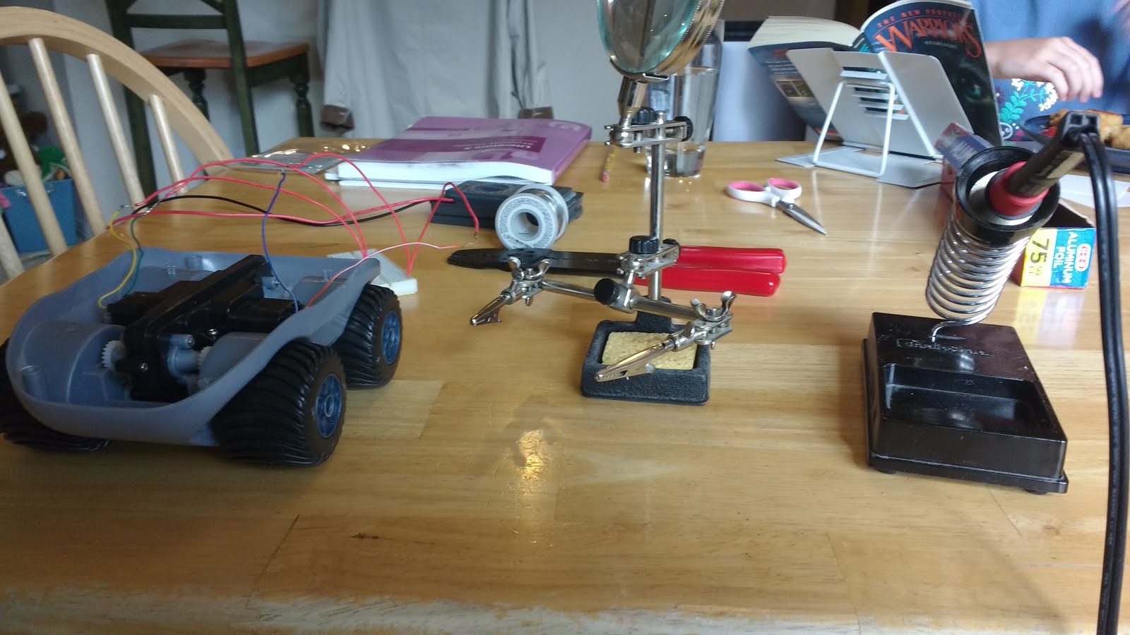
If anyone's interested in my soldering tools, here's a picture:


Here's a list of my equipment:

One 20 watt soldering iron from Radio Shack
One spool of solder, also from Radio Shack
One soldering multi-tool with alligator clippers and magnifying glass... from Radio Shack.
One soldering iron holder... from Radio Shack. Be very careful with the sponge that comes with this. It ate one of my soldering iron tips... You've been warned!

Part 3 will be about my troubleshooting, desperately trying to get the motors to work with Arduino.

As with last time, I have some tips:

1. Plan out what you're going to do beforehand. Don't just shove the soldering iron wherever you see something shiny. ;)

2. Patience is your best friend. Sometimes solder will take a while to absorb enough heat. Give it time. If it heats your fingers holding the solder tube but doesn't melt, maybe you should chop off the tip and keep trying (Works for me.).

3. Be careful to make sure your solder sponge isn't hungry. No idea why, but I've put my hot soldering iron onto the holder's wet sponge... and over time it's eaten away at the iron tip.

4. This might belong in the Part 2, so I'll put it there too: The wires from the motors connect to wires from the brain box via solder. The heat-shrink tubing wasn't connected very well on mine, so I could slide that away from the solder, and after snipping the wires on the brain-box side of the connection, I could just slide the insulation right off.


What should I do with the devil-resistor? Should I...
A: Throw it away
B: Try to get it to explode (Or something exciting) by trying to overload it... I'll include a video.
C: Chop it in half
D: Give the innocent resistor a chance... It's never done anything to me (yet)

Edit: 5/11/16: Updated list of links
Edit: 6/1/16: Updated list of links
Edit: 7/8/16: Updated list of links
Edit: 8/25/16: Updated list of links
Edit: 7/6/17: Updated list of links

Tuesday, April 26, 2016

Arduino Rover Part 1: Initial Plan and Reverse-Engineering.

It's been a while since I've last posted... About nine months. I'll have to get into the habit again.

A few weeks ago, I picked up the Arduino Uno that I've had for a while, and started thinking about what I should build with it. I decided on modifying an old toy rover that I had, and making it wirelessly drivable... but with 2 way audio and a camera feed.

Here's the original rover (Sorry for the low resolution. I don't have any pictures prior to disassembly... Mine was missing a headlight anyway.) It's a shark Kid Galaxy Morphibians toy:
In this first part of several posts, I will be explaining about the insides of this rover after I got clever with a screw-driver.

Links:
Part 1: Initial Plan and Reverse-Engineering
Part 2: Preparing the Rover Chassis
Part 3: Motor Control
Part 4: Bluetooth
Part 5: Mounting
Part 6: Batteries
Part 7: The Test

The first part of disassembly was undoing six screws on the bottomside of the rover. Removing these allowed the top and bottom halves to come apart.

Inside the rover, power wires and antenna connected to a plastic box housing the brains... I couldn't crack it open for fear of breaking everything inside. Then, wires went to two motors, one for each side of the car. After a few glances and attempts to strip the motor wires, it became apparent that all of the wires were both threaded and very thin. Attempts to put them in a breadboard were very discomforting to say the least.


On the physical layout side of things, the battery box, the brain box, and the gearbox took up almost all of the interior space. Not very easy to insert electronics with room to spare. The gearbox was in the middle-bottom, and the battery container was directly on top, eliminating that space almost completely. The brain was at the back, cushioned by foam. Since that's naturally going to have to go, that would seem to be a very good location for batteries to power the Arduino. No way I'm going to be taking the risk of crushing the Arduino itself back there.

I did try to take the gearbox apart, but it reeeally didn't want to open. There might even have been glue inside.


Surprisingly, there were also several more pieces of foam below and around the gearbox, suggesting that the advertising for this particular rover was telling at least part of the truth about potential amphibious capabilities. I'd always kept it out of water anyway, for fear of short circuits.

This rover seems to be pretty well engineered... Too well if I'm going to try to fit my Arduino and a breadboard inside (I'm not).

Part 2 will be about removing the guts and solving the wire-breadboard compatibility issues. It'll involve some soldering.

Until then, I do have some tips on how to go about doing this yourself.

1. There are several different versions of the Kid Galaxy Morphibians... I think Sharks and Gators were the first two to be released. Their internal layout will very likely be the same on all of them.

2. Don't try to open up the brain-box or the gearbox. They're very difficult and you will probably just damage them.

3. This might belong in the Part 2, so I'll put it there too: The motor wires connect to different wires from the brain box via solder. The heat-shrink tubing wasn't connected very well on mine, so I could slide that away from the solder, and after snipping the wires on the brain-box side of the connection, I could just slide the insulation right off.

Edit: 4/28/16: Updated last image
Edit: 5/9/16: Added list of links
Edit: 5/11/16: Updated list of links
Edit: 6/1/16: Updated list of links
Edit: 7/8/16: Updated list of links
Edit: 8/25/16: Updated list of links
        Got bored of just saying "Updated list of links" every single time...
Edit: 7/6/17: Updated... list of... PARTS