This is the sixth part of several posts. I will be explaining about how I set up the power supply of my rover.
Links:
Part 1: Initial Plan and Reverse-Engineering
Part 2: Preparing the Rover Chassis
Part 3: Motor Control
Part 4: Bluetooth!
Part 5: Mounting
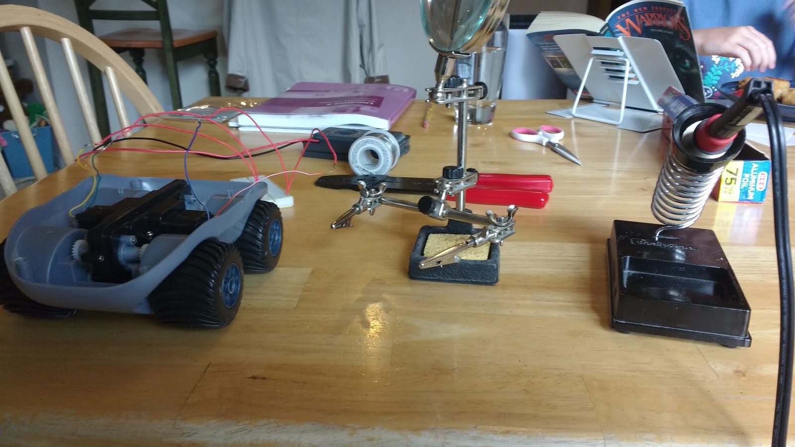
Part 6: Batteries
Part 7: The Test
To start with, here are some facts about the situation:
The rover is only designed to hold three AA batteries (4.5 volts).
According to my multimeter when monitoring the long-disconnected-and-very-bored rover brain, the motors are designed to get the full 4.5 volts from the batteries.
Arduino requires, at the very minimum, a stable supply of more than 5 volts.
This makes it more difficult than I originally thought, which was: "Let's just hook up a 9-volt!" Browsing Google search told me otherwise...
I wasn't about to go looking for how to use a switching regulator, so plan B was to use AAs. Three for the motors and four for Arduino means seven batteries total. That's even more than I remember RC helicopter controllers and the Lego Mindstorms NXT using.
Here's Plan B-and-a-half:
1. Test to see how few batteries can successfully power the motors (Two)
2. Add a single battery to the rover (For a total of four)
3. Have a third wire coming from the middle of the battery chain, thus using all of the batteries to power the board while two of those are also powering the motors when necessary.
4. Do extensive tests with my multimeter to ensure that the voltage never drops below 5 volts. If it does, fiddle with the circuitry until it's stable.
After the test was set up, I found that voltage dropped drastically at the moment I started the motors. Voltage would then very slowly increase as the motors weren't requiring as much power to continue spinning. I added the biggest capacitor I had (1000 μF, also referred to as 1mF). This made good progress, but the capacitor was discharging too quickly. This delayed, but hardly reduced, the voltage drop.
To combat this, I added a 1KΩ resistor between the power / capacitor leads and the Arduino Vin wire. This was a mistake because then, while tests showed satisfactory results, trying to power the Arduino didn't work. The resistor was choking Arduino, and my multimeter couldn't tell because it has a very high internal resistance.
My next attempt was to add the resistor in series with the capacitor, leaving the power wire directly connected to Arduino's Vin pin (Or, at first, the multimeter's lead). This was successful. Charging the capacitor wasn't noticeably affecting results, and voltage would slowly drop, but not to the fatal 5V level, when spinning the motors.
The final test went very well. Arduino turned on. Power was stable. (Manually) activating the motors didn't break anything, and Arduino didn't die when I kept the motors going for several solid seconds. Success!

To get the extra battery into the rover chassis, I had to take a AA holder from another kit, solder it up, and tuck it into the Rover. This would, unfortunately, require me to dismantle the rover in order to change all of the batteries, but it's a personal project. It doesn't need to be super simple, especially since I've already got the Arduino sitting directly on top of the other batteries.
More tips... They just keep coming...
1. Do the math! Connecting random batteries would only have gotten me an overpriced blue paperweight.
2. Know your electrical engineering! The long-standing Kerbal convention of "More Power!" would have lead me to use more batteries rather than a capacitor. This would be less efficient and more likely to overheat the Arduino.
Edit: 7/6/17: Updated list of links